Surveying for all Beginners
Traversing
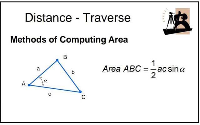
Nearly all surveying needs some computation to lessen the calculation into a more functional form for setting on distance, volumes of earthworks, land areas, etc. A traverse is developed for calculating the distance and inclination joining points that found the perimeter of a site. We will master many different ways to calculate the area inside a traverse.
Fieldwork
- Outfit.
- Transit.
- Measuring set.
- Two line staves.
- Axe, stakes, and nails.
Inspect the articles as executed , or be responsible for defects found upon their return.

Directions
- A field with 7 border, and one rectangular angle. No side less than 500 feet. To enclose from 30 to 40 acres.
Stake out the field
- Given the stakes by A, B, C, D, E, F, and G.
- Documented detail of each stake, and its local location, under its letter, in the rough book. Take four, or more, witnesses to each stake. Record these witnesses with description of stake.
Measure the sides
- Measure down hill.
- As each calculation is made enter it in the 6 column of the documentation on the line with the note in the 3rd column, showing in which direction the calculation will proceeded.

Instrument work
Set up the transit at any station, as A. Back sight to G by means of either clamp and show motion screw, the other clamp being clamped.
Read both plate venires. Document these readings in the two left hand columns of the field notes at the bottom of the page, with a note in the third column that the pointing is from A to G, - all as shown in the form of notes.
Take another look at the venires and back sight, to make sure the pointing is exact and the vernier readings correctly recorded. Release the plate clamp. Set the line the spot on the symbol at B which means the plate clamp and slow motion screw.
Read both plate venires. Document these readings in the 4th and 5th columns of the notes on the next line above the last entry, with a note in the 3rd column to the pointing is from A to B. Release the plate clamp. Set the line of sight again on A G by means of the plate clamp and slow motion screw. Read both plate venires. Watch out if these readings agree sufficiently well with those when the 1st pointing A to G was made. If not, repeat the work till they will.

