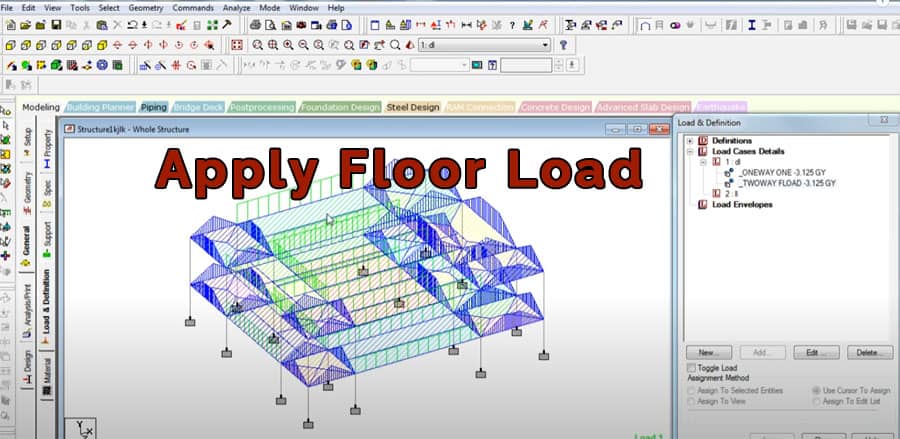
Steps to apply Floor load in Staad pro

Staad pro is a structural designing and analysis software used to design and analyze RCC and steel structures in regard to the respective country code.
Staad pro is one of the frequently used software by structural and civil engineers. The software helps to automate the task of these engineers by terminating the long and tiring procedures of manual methods.
Staad Pro Method for Applying Floor Load to Slab Panels
This article will discuss how we can apply floor loads to slab panels in Staad Pro.
It does not require you to calculate the equivalent load yourself and apply it to the beams bordering the slab. The program calculates the equivalent load automatically and applies it to the beams without any manual calculations. When you apply floor loads to slab panels, the program calculates the equivalent load and applies it uniformly to the beams bordering the slab.
The algorithm will calculate the tributary area and the relevant member loads for these members. For two-way distribution, the floor load is used.
When converting the area/floor load to member load, the following assumptions are made:
- The member load is supposed to be a linearly fluctuating load with distinct magnitudes at the beginning and end.
- MEMBER CABLE, MEMBER TRUSS, MEMBER TENSION, MEMBER COMPRESSION, and CURVED members should not have these loading types specified.
Factors to consider before calculating the floor load transfer in Staad Pro
Whenever the program calculates the tributary load for the slab and beams, it also determines the self-load of each member. Staad Pro moves the floor loads according to the following assumptions:
- The slab should be a two-way slab.
- The load on the member is a linear variation load or a load that varies linearly. The load may have varying magnitudes at the start and end.
- The floor load is being applied to a basic entity, such as a plate, solid, or curved surface, which the structural model does not cover.
In Staad Pro, there are several general formats for assigning loads from floor to slab
In this article, we have given.
In this article, we have given.
f1 f2 = If Y, X, or Z coordinates are specified, all members lying within that global coordinate range will be loaded.
F3 = The unit weight over the square length of the load.
- When a command starts with YRA, this load works hand in hand with the positive global load.
- Load is going to be projected on the plane X-Z.
- Similarly, if you start the command with XRA, this load will behave in the same way as the positive global X. On the Y-Z plane, the load is projected.
- Similarly, ZRA starting commands have a horizontal load in the X-Y plane acting parallel to a positive global Z.
f4, f5, f6, f7: Four corner points define an area upon which the load is supposed to act. These are referred to as global coordinates.
GX, GY, GZ = When a Global direction is incorporated, then the load gets redirected to act in a specified direction or many directions. Accordingly, the magnitude of the loads is based on the area projected on a plane without considering the Global direction.
In the context of the mass definition, the Global direction option is particularly useful.
INCLINED: When you have an inclined floor panel, this value indicates the inclination of the panel relative to the XY, XZ, or YZ global planes.
- In order for the structure to remain perpendicular to the floor planes, the specified global axis has to be modelled.
- Based on the length of the sides, the FLOOR LOAD from a slab is distributed in a triangular or trapezoidal pattern on the adjacent members.
Triangle and Trapezoidal loading patterns for rectangular panels
- Loads per unit area are assumed to be constant for a particular panel, and it is assumed the panel is continuous and without holes.
- First, the CG of the polygon is calculated. Then, each corner of the polygon is connected to the CG, as shown below. We draw a vertical line from the CG to the other side of each triangle.
The area of the triangle will be calculated if the point of intersection of the vertical line and side lies outside the triangle. A uniform distributed load will be applied to the outside corner. Otherwise, the outer side will be loaded triangularly.
To learn more, watch the following video tutorial.
Video Source: Real civil
