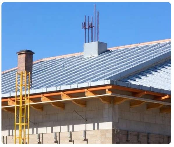
Roof Slab Design Process in Construction

The roof slab design process is a critical component of structural engineering and construction. It involves a comprehensive assessment of loads, material selection, reinforcement layout, and adherence to building codes to ensure structural integrity, durability, and safety.
Understanding the Importance of Roof Slab in a Building
A roof slab serves as the uppermost surface in a structure, protecting against environmental elements and bearing various types of loads. It must be designed to withstand dead loads, live loads, wind loads, and sometimes seismic forces, depending on the geographic location.
Types of Roof Slabs in Construction
Before beginning the design, it's essential to determine the type of slab suitable for the project. Common types include:
- One-way Slab - Supported on two opposite sides; bending occurs in one direction.
- Two-way Slab - Supported on all four sides; bending occurs in two directions.
- Flat Slab - Directly supported by columns without beams.
- Hollow Core Slab - Precast concrete slab with cylindrical voids.
- Waffle Slab - Ribbed slab in two directions; used in large-span areas.
Step-by-Step Roof Slab Design Process
1. Structural Analysis and Load Assessment
The first stage in the roof slab design process involves calculating the various types of loads that the slab will bear:
- Dead Load (DL) - Weight of the slab itself, finishes, and fixed equipment.
- Live Load (LL) - Variable loads from people, furniture, maintenance.
- Wind Load (WL) - Calculated based on height, location, and wind speed.
- Snow Load (if applicable) - Region-specific; crucial in colder climates.
- Seismic Load - Based on zone classification and structure weight.
These loads are computed as per IS 875 or ASCE 7 depending on the region.
2. Selection of Material Grade
The selection of concrete and steel reinforcement must meet the required design strength. Common grades include:
- Concrete: M20, M25, M30 (as per IS 456:2000)
- Steel: Fe415, Fe500 TMT bars
High-quality materials improve durability, reduce shrinkage, and improve crack resistance.
3. Determining Slab Thickness
The thickness of the roof slab directly affects its strength and deflection. General guidelines include:
- Minimum thickness for one-way slabs: 100 mm
- Two-way slabs: 125 - 150 mm
- Flat slabs: May go up to 200 mm depending on the span and load
Thickness is chosen to satisfy bending, shear, and deflection criteria.
4. Span-to-Depth Ratio and Deflection Control
To avoid excessive deflections, span-to-depth ratios must be within permissible limits:
- For simply supported slabs: 20
- For continuous slabs: 26
- For cantilever slabs: 7
These ratios can be adjusted using modification factors based on the percentage of tension reinforcement and concrete type.
5. Design for Flexure (Bending Moment)
Using Limit State Method, the slab is designed for the maximum bending moment (Mu) calculated as:
- Mu = (wL2)/8 for simply supported slabs
- Mu = (wL2)/12 for continuous slabs
Where w = total factored load and L = effective span
Steel reinforcement (Ast) is calculated using:
Ast = Mu / (0.87 x fy x d x (1 - (fy x Ast)/(fck x b x d)))
Where:
- fy = yield strength of steel
- fck = characteristic strength of concrete
- b = width of slab
- d = effective depth

6. Shear Design
If the slab is subjected to heavy loads, shear checks are essential. The nominal shear stress (tv) is calculated and compared with tc from code tables.
If tv > tc, shear reinforcement such as stirrups is added.
7. Reinforcement Detailing
Proper detailing is crucial to ensure the designed strength is achieved in reality. Guidelines include:
- Spacing of main reinforcement: Not more than 3d or 300 mm
- Spacing of distribution steel: Not more than 5d or 450 mm
- Minimum reinforcement: 0.12% of gross cross-sectional area for Fe500
Common bar diameters used: 8 mm, 10 mm, 12 mm for slabs
Cover: 20 mm minimum for roof slabs to protect against corrosion
8. Checking for Deflection and Cracking
Deflection is checked by limiting span/depth ratios. Cracking is controlled by:
- Adequate cover
- Proper placement and anchorage of bars
- Limiting stress in steel to permissible limits
- Using shrinkage and temperature reinforcement
9. Providing Construction and Expansion Joints
For large spans or areas, construction joints and expansion joints are provided to prevent cracking due to thermal movement and shrinkage.
- Expansion joints: Every 30 m to 45 m
- Construction joints: Placed where the bending moment is minimum
10. Concrete Placement and Curing
Proper concrete placement and curing are critical for strength development:
- Vibrators used to remove air voids
- Curing: Minimum of 7 days for ordinary Portland cement and 10 days for blended cement
- Curing methods: Ponding, wet covering, or curing compounds
11. Quality Control and Supervision
Throughout the slab design and construction process, quality control is maintained by:
- Checking formwork alignment and dimensions
- Ensuring correct placement of reinforcement
- Conducting slump test and cube strength test
- Continuous supervision during concrete pouring
12. Compliance with Building Codes
The slab design must strictly adhere to regional building codes and standards such as:
- IS 456:2000
- ACI 318
- BS 8110
- Eurocode 2
These codes ensure that structural integrity, safety, and serviceability are maintained.
Conclusion
The roof slab design process is an intricate task requiring attention to engineering principles, precise calculations, and strict adherence to standards. By thoroughly evaluating load conditions, selecting appropriate materials, and carefully detailing the reinforcement, a safe and durable slab can be constructed. Proper execution during construction and rigorous quality control further ensure the structural longevity of the roof slab.
Please watch the following short video for Roof Slab Design Process in Construction
