What Is Zero Force Member for Truss and How to Identification
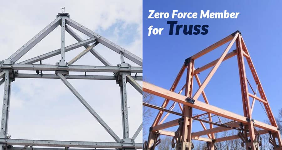
Understanding the behavior of structural members in a truss system is essential for civil engineers, architects, and construction professionals. Among these members, the concept of a zero force member plays a vital role in simplifying calculations, optimizing design, and ensuring stability.
Definition of Zero Force Member in Truss
A zero force member in a truss is a structural member that, under specific loading and support conditions, carries no force. These members do not contribute to resisting external loads directly, but they play important roles in providing stability, maintaining geometry, and distributing loads when conditions change.
Although they may appear unnecessary at first glance, zero force members are often intentionally placed in trusses to ensure rigidity and to prevent collapse in cases where loading conditions vary.
Importance of Zero Force Members in Structural Engineering
Zero force members are not just redundant elements; they serve several critical purposes:
- Maintaining Structural Stability: They prevent excessive deformation and keep the truss in its designed shape.
- Future Load Adaptability: A truss may encounter loads in different directions during its service life. Zero force members become active when new loads are applied.
- Simplification of Analysis: Recognizing zero force members reduces the complexity of truss analysis by eliminating unnecessary calculations.
- Support Against Buckling: In long members, they act as bracing to avoid buckling.
Basic Rules for Identifying Zero Force Members
There are well-established rules that allow engineers to quickly identify zero force members without solving the entire truss system. The method of joints is commonly used for this purpose.

Rule 1: Two Non-Collinear Members at a Joint with No External Load
If two non-collinear members meet at a joint and no external load or support reaction is applied at that joint, then both members are zero force members.
Example: If members AB and AC meet at joint A with no external load at A, both AB and AC carry no force.
Rule 2: Three Members with Two Collinear Members
If three members meet at a joint, where two of them are collinear and no external load or support reaction is present at the joint, then the non-collinear member is a zero force member.
Example: At joint B, if members AB and BC are collinear and member BD is inclined, then BD is a zero force member.
Rule 3: Symmetry and Loading Conditions
In a symmetrical truss with symmetrical loading, certain members may become zero force members because of symmetry. Identifying these requires understanding both geometry and applied loads.
Rule 4: Advanced Situations
In more complex trusses, zero force members can sometimes be identified by a combination of the above rules or by considering equilibrium equations (SFx = 0, SFy = 0).
Step-by-Step Identification of Zero Force Members
- Start at Simple Joints: Begin with joints that have only two or three members.
- Apply Rule 1 and Rule 2: Use the established rules to eliminate members that do not carry force.
- Check Symmetry: Identify symmetrical conditions in the truss.
- Reevaluate After Eliminations: After removing identified zero force members, some other joints may now satisfy the rules.
- Confirm with Equilibrium Equations: Double-check by applying force balance equations if necessary.
Illustrative Examples of Zero Force Members
Example 1: Warren Truss
In a simple Warren truss, certain diagonal members can be zero force members when the load is applied at specific joints.
Example 2: Pratt Truss
In a Pratt truss under vertical loading, some diagonals that are not aligned with load paths may carry no force and hence act as zero force members.
Example 3: Bridge Truss with No Central Load
If the load is not applied at the center of the truss, some diagonal bracing elements may remain zero force members.
Applications of Zero Force Members in Real Structures
Zero force members are widely used in different types of civil and mechanical engineering structures, including:
- Bridge Trusses: To provide stability against lateral loads and buckling.
- Roof Trusses: To resist wind and snow loads under varying conditions.
- Cranes and Towers: To enhance rigidity and reduce sway.
- Aircraft and Space Frames: To reduce weight while maintaining strength.
Advantages of Identifying Zero Force Members
- Time-Saving in Analysis: By eliminating unnecessary members, the number of calculations is reduced.
- Efficient Material Usage: Understanding their function helps engineers avoid overdesign.
- Enhanced Safety: Even though they carry no force under normal conditions, they act as backup support in case of unexpected load applications.
- Economic Design: Leads to cost-effective structural systems by balancing strength and material economy.
Practical Considerations in Design
While identifying zero force members theoretically is straightforward, in practice engineers must consider:
- Unexpected Loads: A member identified as zero force may carry load under wind, seismic, or accidental forces.
- Construction Tolerances: Small deviations in fabrication may induce forces in theoretically zero members.
- Dynamic Effects: Vibrations and moving loads can activate zero force members.
Thus, removing them blindly from design is not recommended unless load paths are completely verified.
Conclusion
Zero force members in trusses are fundamental to structural analysis and design. By applying basic rules and equilibrium equations, engineers can quickly identify them and simplify calculations. However, these members should never be underestimated, as they provide stability, adaptability, and safety under varying conditions.
A strong understanding of zero force members ensures that trusses are not only efficient in terms of material but also reliable in real-world applications.
Please watch the following short video for Zero Force Member for Truss
Also Read: