Spillway in Civil Engineering: Types, Components, Design Principles, and Construction Details
Introduction to Spillway in Civil Engineering
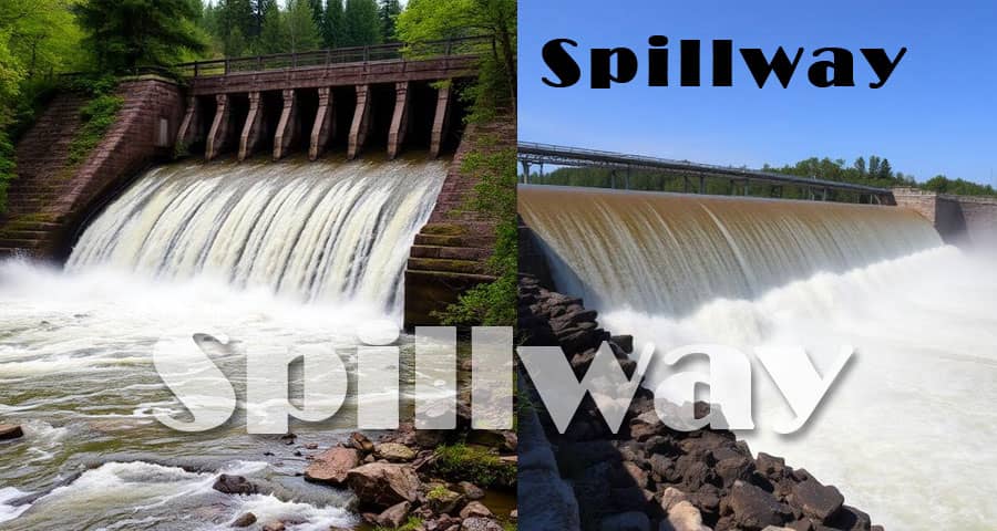
A spillway in civil engineering is a critical hydraulic structure constructed to safely release excess water from dams, reservoirs, and barrages to downstream areas. We design spillways to prevent overtopping of dams, which can lead to catastrophic structural failure. In modern water resources engineering, spillways are not merely overflow channels; they are precisely engineered systems that manage flood discharge, regulate reservoir levels, and protect infrastructure and human settlements.
Spillways are essential components in major dam projects worldwide, including the Bhakra Dam and the Hoover Dam, where carefully designed spillway systems ensure flood safety and operational reliability. We focus on hydraulic efficiency, structural integrity, and energy dissipation when designing spillways to handle extreme flood events.
Primary Functions of a Spillway
We incorporate spillways in dam structures to perform the following essential functions:
- Controlled release of surplus water
- Protection against dam overtopping
- Flood routing and reservoir regulation
- Prevention of upstream and downstream damage
- Energy dissipation to minimize erosion
By maintaining controlled discharge, spillways ensure long-term stability of gravity dams, arch dams, and embankment dams.
Classification of Spillways in Civil Engineering
Spillways are classified based on structural configuration, hydraulic behavior, and method of discharge control.
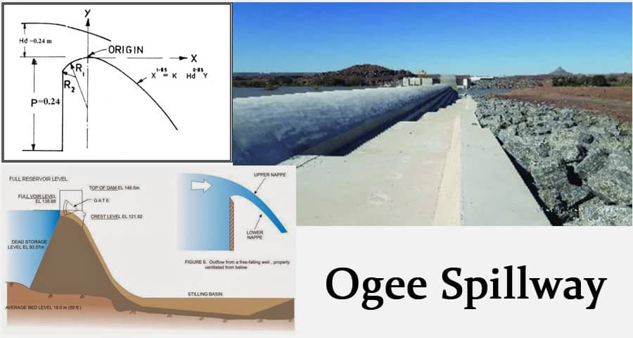
1. Ogee Spillway (Overflow Spillway)
An ogee spillway is integrated with concrete gravity dams and features an S-shaped crest profile matching the lower nappe of water. We design this type to optimize hydraulic flow and minimize negative pressure beneath the water jet.
Key Characteristics:
- Suitable for concrete dams
- High discharge efficiency
- Smooth curvature reduces cavitation
- Requires proper downstream energy dissipation
Ogee spillways are widely adopted in large dams such as the Tehri Dam.
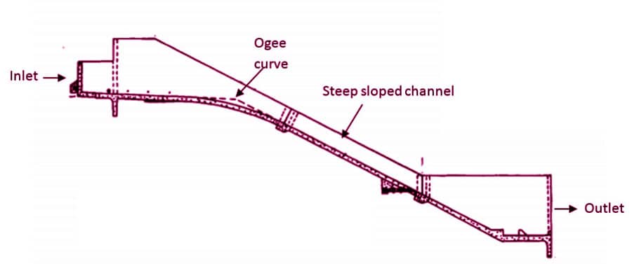
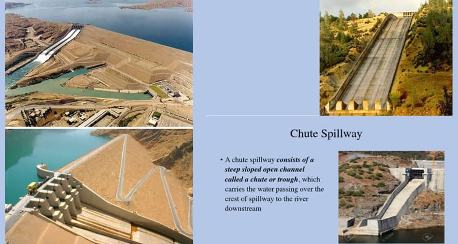
2. Chute Spillway (Trough Spillway)
A chute spillway conveys water through a steep concrete channel placed along the abutment or downstream face of the dam.
Advantages:
- Ideal for earthfill and rockfill dams
- Simple hydraulic design
- Economical construction
- Suitable for large flood discharge
We provide adequate training walls and energy dissipators to prevent erosion at the toe.
3. Side Channel Spillway
A side channel spillway collects water over a crest and carries it parallel to the dam axis before directing it downstream.
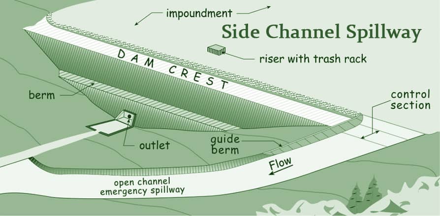
Applications:
- Sites with narrow valleys
- Limited space availability
- Moderate flood discharge
We use this type when topographic constraints restrict direct overflow alignment.
4. Shaft Spillway (Morning Glory Spillway)
A shaft spillway, commonly known as a morning glory spillway, consists of a vertical shaft connected to a horizontal tunnel.
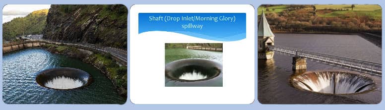
Features:
- Compact design
- Suitable for narrow gorges
- Efficient for high-head dams
- Requires precise structural detailing
This design is notably seen in high-elevation reservoirs worldwide.
5. Siphon Spillway
A siphon spillway operates automatically once water reaches a specific level. We design it using inverted U-shaped pipes that initiate flow through siphonic action.
Advantages:
- Automatic regulation
- No gates required
- Efficient for moderate reservoirs
However, careful air venting is essential to maintain consistent operation.
Main Components of a Spillway
We design spillways with multiple structural and hydraulic elements:
1. Crest Structure
The crest determines discharge capacity. Its profile may be ogee-shaped or straight, depending on hydraulic design.
2. Control Gates
We use radial gates, vertical lift gates, or drum gates to regulate water release.
3. Approach Channel
Ensures smooth flow toward the crest without turbulence or flow separation.
4. Discharge Channel
Conveys water safely downstream.
5. Energy Dissipation Structures
Includes:
- Stilling basins
- Flip buckets
- Baffle blocks
- Hydraulic jump basins
Energy dissipation is crucial to prevent downstream scouring.
Hydraulic Design Considerations for Spillways
We base spillway design on hydrological and hydraulic parameters.
1. Design Flood Estimation
We determine the Probable Maximum Flood (PMF) using rainfall-runoff analysis and historical data.
2. Discharge Capacity Calculation
The fundamental discharge equation:
Q = CLH3/2
Where:
- Q = Discharge
- C = Coefficient of discharge
- L = Effective crest length
- H = Head over crest
3. Cavitation Prevention
We incorporate aerators and smooth surfaces to prevent cavitation damage.
4. Structural Stability
We analyze uplift pressure, sliding, overturning, and foundation stresses.
Energy Dissipation Methods in Spillways
Energy dissipation prevents severe erosion downstream.
Hydraulic Jump Formation
We create controlled hydraulic jumps in stilling basins.
Flip Bucket Design
Used in high dams to project water away from the toe.
Roller Buckets
Used when tailwater conditions are favorable.
Each method depends on flow velocity, tailwater depth, and geological conditions.
Construction Procedure of Spillway
We follow systematic stages:
- Excavation and Foundation Preparation
- Formwork and Reinforcement Placement
- Concrete Pouring and Compaction
- Gate Installation
- Surface Finishing and Aerator Placement
- Hydraulic Testing and Commissioning
Quality control during construction ensures long-term performance.
Advantages of Proper Spillway Design
- Dam safety assurance
- Flood mitigation
- Extended structural lifespan
- Reduced maintenance costs
- Improved operational flexibility
Modern spillway systems incorporate automation and remote monitoring technologies.
Common Spillway Failures and Preventive Measures
We prevent failures through careful design and inspection.
1. Overtopping
Prevented by adequate crest elevation and discharge capacity.
2. Cavitation Damage
Avoided using aeration devices.
3. Structural Cracks
Controlled through proper reinforcement detailing.
4. Foundation Erosion
Mitigated by cutoff walls and protective aprons.
Regular inspection programs significantly reduce risks.
Spillway vs. Outlet Works
A spillway releases excess floodwater, while outlet works regulate normal reservoir discharge for irrigation, water supply, and hydropower.
Both systems operate together but serve distinct hydraulic functions.
Modern Innovations in Spillway Engineering
We integrate advanced technologies such as:
- Fuse plug spillways
- Labyrinth spillways
- Roller-compacted concrete spillways
- Automated gate control systems
Labyrinth spillways increase crest length without increasing width, enhancing discharge capacity efficiently.
Conclusion
A spillway in civil engineering is a vital safety and hydraulic structure that protects dams from failure. We design spillways with precise hydraulic calculations, robust structural detailing, and effective energy dissipation systems. From ogee spillways to shaft spillways, each type serves specific site conditions and hydrological requirements.
Comprehensive design, quality construction, and regular inspection ensure that spillways perform reliably under extreme flood conditions. By integrating advanced engineering techniques, we enhance safety, sustainability, and operational efficiency in dam infrastructure worldwide.
Please watch the following short video for Spillway in Civil Engineering
Also Read:
![]() Difference Between Azimuths and Bearings in Surveying
Difference Between Azimuths and Bearings in Surveying
![]() Why Is Structural Engineering Important in Architectural Design?
Why Is Structural Engineering Important in Architectural Design?
![]() What can replace wood for building materials?
What can replace wood for building materials?
![]() Types of Wall Finishes - A Complete Guide for Modern Interiors and Exteriors
Types of Wall Finishes - A Complete Guide for Modern Interiors and Exteriors
![]() Volume Batching of Concrete: A Complete Guide for Quality Concrete Mixes
Volume Batching of Concrete: A Complete Guide for Quality Concrete Mixes